A Pressure Relief Valve (PRV) in accordance with API 2000 is a type of pressure protection device designed primarily for atmospheric and low-pressure storage tanks that contain non-refrigerated, low-pressure volatile liquids. Its primary function is to relieve excessive internal pressure or admit air/vapor during vacuum conditions, thereby preventing tank rupture or implosion.
API 2000, titled “Venting Atmospheric and Low-Pressure Storage Tanks”, provides the design and performance requirements for such valves. These PRVs are often combined with vacuum relief functions and are key to maintaining the integrity and safety of storage tanks.
Tank Protection: Prevents overpressure and vacuum collapse in accordance with API-recommended venting capacities.
Product Conservation: Minimizes product loss by only venting when pressure or vacuum limits are exceeded.
Safety Assurance: Reduces risk of fire, explosion, or environmental contamination due to structural tank failure.
Compliance with API 2000: Ensures conformity with industry-accepted engineering practices.
Low Maintenance & Passive Operation: Functions without external power or control systems.
Customizable Settings: Relief set pressures can be tailored to specific tank conditions and fluid characteristics.
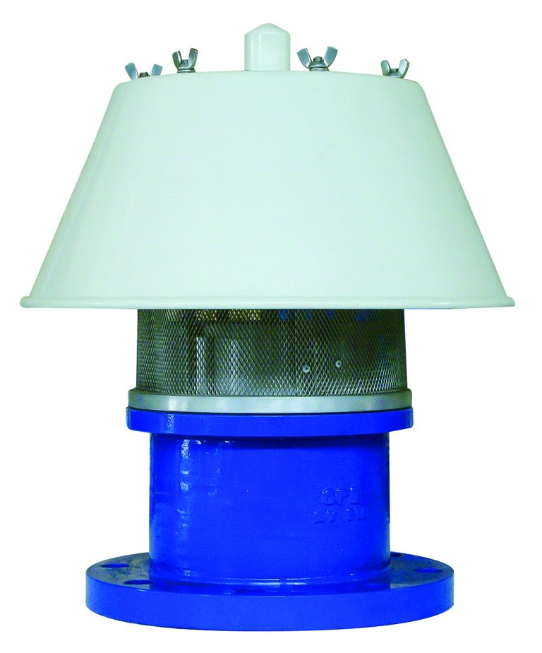
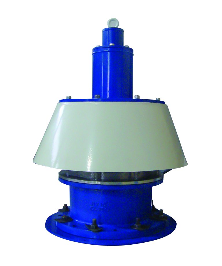
Pressure-Only Relief Valve
Vacuum-Only Relief Valve
Spring-loaded or Weight-loaded
Flame Arrester Separately(optional)
End-of-line or In-line Mounted
Petroleum Storage Terminals
Chemical and Petrochemical Storage Tanks
Ethanol and Biofuel Storage
Paint and Coating Storage Facilities
Pharmaceutical and Food-grade Liquid Tanks
Water and Wastewater Plants with Low-pressure Gas Holders
PRVs per API 2000 are especially relevant for fixed-roof tanks, cone-roof tanks, or tanks with internal floating roofs, which are exposed to pressure fluctuations due to filling/emptying or atmospheric changes.
| Feature | Typical Values / Notes |
|---|---|
| Applicable Standard | API 2000, ISO 28300 |
| Set Pressure Range | Pressure: 50 mm W.G up to 2500 mm W.G (customizable) |
| Vacuum Setting Range | 25 mm W.G up to 500 mm W.G |
| Valve Size Range | 2” to 12” (DN 50–DN 300) |
| Materials | Aluminum, stainless steel, carbon steel |
| Seal Materials | PTFE, FKM (Viton), Buna-N, EPDM |
| Mounting Types | ANSI/DIN flanged, threaded, or welded |
| Flow Capacity (SCFH/m³/h) | Determined using GPE Catalogue |
| Configuration | End-of-line (at tank outlet) or inline |
| Optional Features | Flame arrester, weather hood, lifting lever |
Mount the valve vertically on the tank’s vent nozzle, ensuring a proper seal.
Set pressure and vacuum points per tank venting requirements determined via API 2000 calculations.
Ensure the vent line is free from obstructions, and outlet is safely directed.
Install in conjunction with blanketing gas systems where applicable.
Use flame arresters or gas-tight models in flammable vapor service.
Visual Inspection every 6 months for corrosion, damage, or blockage.
Functional Testing annually or per site safety procedures.
Seal Replacement when cracked, hardened, or chemically attacked.
Cleaning of valve seat and internal guide areas to prevent sticking or misalignment.
Keep records of set pressure validation and recalibration as part of process safety management (PSM).
VOC Emission Control: Reduces unnecessary product vapor loss during storage.
Prevents Tank Failures: Avoids large-scale spills or structural damage caused by overpressure or vacuum.
Supports Regulatory Compliance: Meets environmental mandates like U.S. EPA’s NSPS (40 CFR 60 Subpart Kb).
Low Operational Footprint: Mechanical devices with no need for energy input.
Made from Recyclable Metals: Aluminum and stainless-steel body materials can be fully recycled.
Long Lifespan: Corrosion-resistant materials and modular components reduce replacement frequency.
Replaceable Components: Internals (seals, springs, pallets) can be serviced without discarding the entire unit.
Eco-Friendly Configurations: Options for closed venting to flare or vapor recovery systems.
Leaking Valves may result in fugitive emissions.
Incorrect Settings can lead to tank implosion or overfill pressure venting.
Clogged Outlets can prevent proper relief, causing safety hazards.