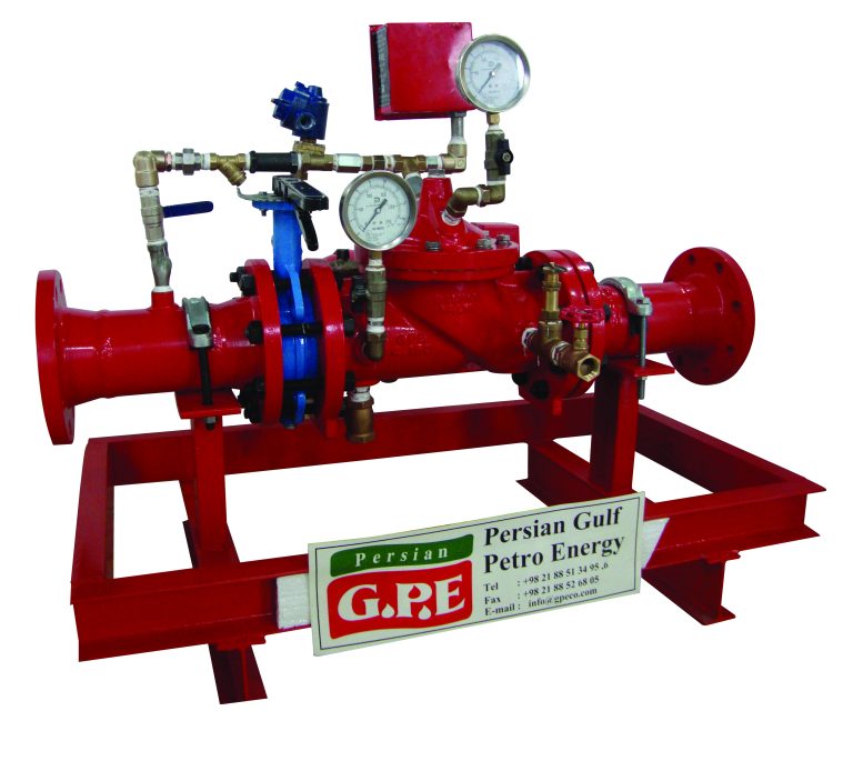
The GPE deluge valve is a diaphragm valve that operates hydraulically and allows for quick release. It consists of three chambers including inlet, outlet and top/priming chamber which are separated from each other by the diaphragm-operated clapper and seat seal. When in the SET position, water pressure is transmitted from the system supply side to the top chamber through an external bypass check valve and restriction orifice. This allows the supply pressure in the top chamber act on the diaphragm-operated clapper, which holds the seat against the inlet supply pressure due to the differential pressure design. In the event of a fire detection, the top chamber is released through the outlet port by opening the actuation devices. The pressure in the top chamber cannot be refilled through the restricted inlet port, and the upward force of the supply pressure lifts the clapper, enabling water flow to the system piping network and alarm devices.
A deluge valve is a type of system control valve utilized in deluge systems to rapidly apply water in a spray pattern. It serves as a protective measure for various areas, including power transformer installations, storage tanks, conveyor systems, and other industrial applications. The deluge valve can also be employed to safeguard aircraft hangars and combat fires involving flammable liquids by incorporating a foaming agent.
| ID | TRIM COMBINATION | MOUNTING POSITION |
| V-WB | Wet Pilot Trim + Solenoid Valve* + Pressure Switch* | Vertical |
| H-WB | Horizontal | |
| V-DB | Dry Pilot Trim + Solenoid Valve* + Pressure Switch* | Vertical |
| H-DB | Horizontal | |
| V-WT | Wet Pilot Trim + Test & Alarm Trim + Solenoid Valve*
+ Pressure Switch* |
Vertical |
| H-WT | Horizontal | |
| V-DT | Dry Pilot Trim + Test & Alarm Trim + Solenoid Valve*
+ Pressure Switch* |
Vertical |
| H-DT | Horizontal | |
| V-WD | Wet Pilot Trim + Drip & Drain Trim + Solenoid Valve*
+ Pressure Switch* |
Vertical |
| H-WD | Horizontal | |
| V-DD | Dry Pilot Trim + Drip & Drain Trim + Solenoid Valve*
+ Pressure Switch* |
Vertical |
| H-DD | Horizontal | |
| V-WTD | Wet Pilot Trim + Test & Alarm Trim + Drip & Drain Trim + Solenoid Valve* + Pressure Switch* | Vertical |
| H-WTD | Horizontal | |
| V-DTD | Dry Pilot Trim + Test & Alarm Trim + Drip & Drain Trim + Solenoid Valve* + Pressure Switch* | Vertical |
| W-DTD | Horizontal |
The wet and dry pilot trims are the essential basic trims needed to operate the deluge valve. The inclusion of an electric solenoid valve for remote actuation and a pressure switch for sensing and notification are not mandatory but can be added as optional features.
These types of trims are a combination of basic wet and dry pilot trims together with the drip and drain trim. The inclusion of an electric solenoid valve for remote actuation and a pressure switch for sensing and notification are not mandatory but can be added as optional features.
These types of trims are a combination of basic wet and dry pilot trims together with the test and alarm trim. The inclusion of an electric solenoid valve for remote actuation and a pressure switch for sensing and notification are not mandatory but can be added as optional features.
These types of trims are a combination of basic wet and dry pilot trims together with the test and alarm trim as well as the drip and drain trim. The inclusion of an electric solenoid valve for remote actuation and a pressure switch for sensing and notification are not mandatory but can be added as optional features.
| Model | 4920 | |
| Nominal Pipe Size | 200, 150, 100, 80, 50 NB | |
| Operating Pressure Range | 1.4 to 17.5 kg/cm2 (20 to 250 psi) | |
| End Connection Type | Flange × Flange | |
| THREADED OPENING TYPE | BSPT | |
| MOUNTING TYPE | Vertical/Horizontal | |
| HYDROSTATIC TEST PRESSURE | 35 kg/cm2 (500 psi) | |
| FLANGE CONNECTION TYPE | ANSI B 16.5 #150 RF and FF is Standard Supply (Contact GPE Sales for other options) | |
| WET PILOT SPRINKLER HEIGHT LIMITATION | See GPE Catalogue | |
| NET WEIGHT (WITHOUT TRIM) | 200 NB | 336 kg |
| 150 NB | 134 kg | |
| 100 NB | 82 kg | |
| 80 NB | 59 kg | |
| 50 NB | 28 kg | |
| FINISH COLOR | Red to RAL 3001 | |
The system pipeline must be thoroughly flushed before putting the deluge valve into service. The system should be commissioned by a qualified and trained individual. Following several initial successful tests, training for system inspection and testing must be provided to an authorized person. Regular system inspections and testing, in accordance with NFPA guidelines or local jurisdiction regulations, are recommended.
Only authorized and trained personnel are permitted to conduct inspection and testing. Under no circumstances should the water supply or any valves be shut off for repairs or testing without presence a roving security and fire watch team in the area. Additionally, local security personnel and the central alarm station should be notified to prevent false alarm signals.
It is recommended to visually inspect the system at least twice a week. During the inspection, make sure all control valves are correctly positioned according to system requirements and check for any signs of damage to components.
inspections need to be more frequent when there are contaminated water supplies, corrosive/scaling water supplies, and corrosive atmospheres.